


SIPART PS2
SIPART PS2
One that masters everything
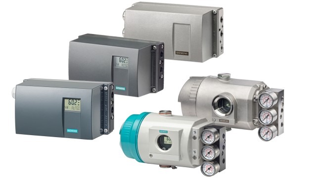
The SIPART PS2 is the most widely used valve positioner for linear and part-turn actuators in industrial applications. It has proved reliable in many valve control applications thanks to its diagnostics capability and extensive range of functions. The all-round positioner of Siemens is well equipped - even for extreme ambient conditions. The following enclosure options are available: Polycarbonate, Aluminum, Stainless steel, Flameproof aluminum or 316L stainless steel.
SIPART PS2 electropneumatic positioner in polycarbonate enclosure with aluminum gauge block (optional)

SIPART PS2 electropneumatic positioner in aluminum enclosure

SIPART PS2 electropneumatic positioner in stainless steel enclosure with stainless steel gauge block (optional)

SIPART PS2 electropneumatic positioner in flameproof aluminum enclosure (Ex d) with aluminum gauge block (optional)

SIPART PS2 electropneumatic positioner in flameproof stainless steel enclosure 316L with stainless steel gauge block (optional)
The SIPART PS2 electropneumatic positioners are used to control the process valve or damper position of pneumatic linear or part-turn actuators or via positioning cylinder according to the setpoint specification. A digital input can trigger holding of the position or approach of the safety setting of the process valve.
Benefits
SIPART PS2 positioners offer decisive advantages:
- Simple mounting and automatic commissioning
- Simple operation and configuration of the device using 3 buttons and one 2-line local display or via SIMATIC PDM
- Very high control performance
- Negligible air consumption in stationary operation
- "Tight closing" function ensures maximum positioning pressure on the process valve seat
- "Fast Open/Fast Close" function for defined approach of the end position with fast reaction to new setpoint specifications
- "Fail in Place" function:
Maintain current position on failure of electrical and/or pneumatic auxiliary power - Numerous functions can be activated by simple configuring (e.g. characteristic curves and limits)
- One device variant for linear and part-turn actuators
- Insensitive to vibrations due to few moving parts and optionally with wear-free position detection
- External non-contacting sensor as option for extreme ambient conditions
- "Intelligent solenoid valve": Solenoid valve function and diagnostics in one device
- Extensive diagnostic functions for process valve and actuator, e.g.:
- Full Stroke Test
- Multi Step Response Test
- Valve Performance Test
- Valve Signature, pressure sensor-aided
- Partial Stroke Test e.g. for safety process valves (also pressure sensor-aided) for performance and maintenance evaluation of the valve
- Can be operated with natural gas, carbon dioxide, nitrogen or noble gases
- SIL (Safety Integrity Level) 2
-----------------------------------------------------------------------------------
Application
The SIPART PS2 positioner is used worldwide on all pneumatic actuators, in all applications and industries:
- Chemical industry
- Petrochemical industry
- Oil and gas
- Water/wastewater industry
- Power supply
- Pharmaceutical industry
- Food, beverage and tobacco industries
The devices are available in variants for:
- 4 to 20 mA
- HART communication
- PROFIBUS PA communication
- FOUNDATION Fieldbus (FF) communication
- Single-and double-acting valves in various enclosure designs and various materials (polycarbonate, aluminum and stainless steel)
- Applications without explosion protection requirements
- Hazardous applications in the versions:
- Device protection with intrinsic safety (Ex i)
for use in Zone 1, 2, 21, 22 or Class I, II, III/Division 1/Groups A-G - Device dust ignition protection by enclosure (Ex t)
type of protection for use in Zone 21, 22 or Class II, III/Division 1/Groups E-G - Device protection with increased security (Ex e)
for use in Zone 2 or Class I, Division 2, Groups A-D - Device protection with flameproof enclosure (Ex d)
for use in Zone 1 or Class I, Division 1, Groups A-D
- Device protection with intrinsic safety (Ex i)
Stainless steel enclosure for extreme ambient conditions
The SIPART PS2 is available in a stainless steel enclosure for use in particularly aggressive environments (e.g. offshore operation, chlorine plants). The device functionality is not different due to the enclosure variants.
Technical specifications
SIPART PS2 (all device designs)
Operating conditions | |
Ambient conditions | For indoor and outdoor use |
Ambient temperature | In hazardous areas, observe the maximum permissible ambient temperature according to the temperature class. |
| ‑30 ... +80 °C (‑22 ... +176 °F) |
| ≤ 2 000 m above mean sea level. |
| 0 ... 100% |
Type of protection2) | IP66/Type NEMA 4X |
Corrosion protection according to EN ISO 9227:2012 and EN ISO 12944:1999 |
|
| C5‑M medium durability |
| C5‑M medium durability |
| C5‑M high durability |
Mounting position | Any. Electrical connections and exhaust opening not facing up in wet environment (outdoor/rain). |
Vibration resistance |
|
| 3.5 mm (0.14"), 2 ... 27 Hz, 3 cycles/axis 98.1 m/s² (321.84 ft/s²), 27 ... 300 Hz, 3 cycles/axis |
| 150 m/s² (492 ft/s²), 6 ms, 1 000 shocks/axis |
| 10 ... 200 Hz; 1 (m/s²)²/Hz (3.28 (ft/s²)²/Hz) 200 ... 500 Hz; 0.3 (m/s²)²/Hz (0.98 (ft/s²)²/Hz) 4 hours/axis |
| ≤ 30 m/s² (98.4 ft/s²) without resonance sharpness |
Climatic class | According to IEC EN 60721‑3 |
| 1K5, but ‑40 … +80 °C (1K5, but ‑40 … +176 °F) |
| 2K4, but ‑40 … +80 °C (2K4, but ‑40 … +176 °F) |
Pneumatic data | |
Auxiliary power (inlet air) | Compressed air, carbon dioxide (CO2), nitrogen (N2), noble gases or natural gas |
| 1.4 ... 7 bar (20.3 ... 101.5 psi) |
Air quality according to ISO 8573‑1 |
|
| Class 3 |
| Class 3 (min. 20 K (36 °F) below ambient temperature) |
| Class 3 |
Unrestricted flow (DIN 1945) |
|
|
|
| 4.1 Nm³/h (18.1 USgpm) |
| 7.1 Nm³/h (31.3 USgpm) |
| 9.8 Nm³/h (43.1 USgpm) |
|
|
| 8.2 Nm³/h (36.1 USgpm) |
| 13.7 Nm³/h (60.3 USgpm) |
| 19.2 Nm³/h (84.5 USgpm) |
|
|
| 4.3 Nm³/h (19.0 USgpm) |
| 7.3 Nm³/h (32.2 USgpm) |
| 9.8 Nm³/h (43.1 USgpm) |
Restrictor ratio | Adjustable |
Auxiliary power consumption in the controlled state | < 0.036 Nm³/h (0.158 USgpm) |
Sound pressure | LAeq < 75 dB LAmax < 80 dB |
Sound pressure with installed Siemens booster | LAeq < 95 dB LAmax < 98 dB |
Structural design | |
Mode of operation |
|
| 3 ... 130 mm (0.12 ... 5.12 inch); greater stroke range on request |
| 30 ... 100° (up to 180° on request) |
Mounting type |
|
| Using mounting kit 6DR4004‑8V and where necessary with an additional lever arm 6DR4004‑8L on actuators according to IEC 60534‑6‑1 (NAMUR) with ribs, bars or flat face. |
| Using mounting kit 6DR4004‑8D or TGX:16300‑1556 on actuators with mounting plane according to VDI/VDE 3845 and IEC 60534‑6‑2: The actuator-specific mounting console 6DR4004‑1D ... 4D must be ordered separately, see the selection and ordering data. |
Weight, positioner without option modules or accessories |
|
| Approx. 0.9 kg (1.98 lb) |
| Approx. 1.3 kg (2.86 lb) |
| Approx. 3.9 kg (8.6 lb) |
| Approx. 1.6 kg (3.53 lb) |
| Approx. 5.2 kg (11.46 lb) |
| Approx. 8.4 kg (18.5 lb) |
Material |
|
Dimensions | See "Dimensional drawings" |
Device designs |
|
| Single-acting and double-acting |
| Single-acting |
| Single-acting and double-acting |
| Single-acting and double-acting |
Gauge block |
|
|
|
| IP31 |
| IP44 |
| IP54 |
| According to EN 837‑1 |
Connections, electrical |
|
| 2.5 mm2 AWG30‑14 |
|
|
| M20x1.5 or ½‑14 NPT |
| Ex d-certified M20x1.5; ½-14 NPT or M25x1.5 |
Connections, pneumatic | Female thread G¼ or ¼‑18 NPT |
Controller | |
Controller unit |
|
| Adaptive |
|
|
| Adaptive |
| Can be set as fixed value |
Analog-to-digital converter |
|
| 10 ms |
| ≤ 0.05% |
| ≤ 0.2% |
| ≤ 0.1%/10 K (≤ 0.1%/18 °F) |
Certificates and approvals | |
Classification according to pressure equipment directive (PED 2014/68/EU) | For gases of fluid group 1, complies with requirements of article 4, paragraph 3 (sound engineering practice SEP) |
CE conformity | You can find the appropriate directives and standards, including the relevant versions, in the EC Declaration of Conformity on the Internet. |
UL conformity | You can find the appropriate directives and standards, including the relevant versions, in the UL-CERTIFICATE OF COMPLIANCE on the Internet. |
Explosion protection | |
Explosion protection according to ATEX/IECEx | Depending on the device design; see "Explosion protection" section |
Natural gas as driving medium | For technical specifications using natural gas as driving medium, see operating instructions. |
1) At ≤ ‑10 °C (≤ 14 °F), the refresh rate of the local display is limited. When using Analog Output Module (AOM), only T4 is permissible.
2) Max. impact energy 1 joule for enclosure with inspection window 6DR5..0 and 6DR5..1 or max. 2 joules for 6DR5..3.
3) The following applies to fail in place double acting: 3 ... 7 bar (43.5 ... 101.5 psi)
4) When using Ex d versions (6DR5..5‑... and 6DR5..6‑...), values are reduced by approximately 20%.
SIPART PS2 with 4 ... 20 mA / HART
Electronics without explosion protection | Electronics with explosion protection Ex d | Electronics with explosion protection Ex i | Electronics with explosion protection Ex i, Ex e, Ex t | |
|---|---|---|---|---|
Electrical specifications |
| |||
Current input IW |
| |||
| 4 ... 20 mA | |||
| 840 V DC, 1 s | |||
| Suitable only for floating contact; max. contact load | |||
2-wire connection (terminals 6/8) |
| |||
Current to maintain the auxiliary power supply | ≥ 3.6 mA | |||
Required load voltage UB |
| |||
|
| |||
| 6.36 V (= 318 Ω) | 6.36 V (= 318 Ω) | 7.8 V (= 390 Ω) | 7.8 V (= 390 Ω) |
| 6.48 V (= 324 Ω) | 6.48 V (= 324 Ω) | 8.3 V (= 415 Ω) | 8.3 V (= 415 Ω) |
|
| |||
| 7.9 V (= 395 Ω) | - | - | - |
| 8.4 V (= 420 Ω) | - | - | - |
|
| |||
| 6.6 V (= 330 Ω) | 6.6 V (= 330 Ω) | - | - |
| 6.72 V (= 336 Ω) | 6.72 V (= 336 Ω) | - | - |
|
| |||
| - | 8.4 V (= 420 Ω) | 8.4 V (= 420 Ω) | 8.4 V (= 420 Ω) |
| - | 8.8 V (= 440 Ω) | 8.8 V (= 440 Ω) | 8.8 V (= 440 Ω) |
| ± 40 mA | ± 40 mA | - | - |
Effective internal capacitance Ci |
| |||
| - | - | 11 nF | "ic": 11 nF |
| - | - | 11 nF | "ic": 11 nF |
Effective internal inductance Li | ||||
| - | - | 209 µH | "ic": 209 µH |
| - | - | 312 µH | "ic": 312 µH |
For connecting to circuits with the following peak values | - | - | Ui = 30 V | "ic": "ec"/"t": |
3-/4-wire connection (terminals 2/4 and 6/8) 6DR53..; 4 ... 20 mA, not explosion-proof |
| |||
Load voltage at 20 mA | ≤ 0.2 V (= 10 Ω) | ≤ 0.2 V (= 10 Ω) | ≤ 1 V (= 50 Ω) | ≤ 1 V (= 50 Ω) |
Auxiliary power UAux | 18 ... 35 V DC | 18 ... 35 V DC | 18 ... 30 V DC | 18 ... 30 V DC |
Current consumption IH | (UAux -7.5 V)/2.4 kΩ [mA] | |||
Effective internal capacitance Ci | - | - | 22 nF | 22 nF |
Effective internal inductance Li | - | - | 0.12 mH | 0.12 mH |
For connecting to circuits with the following peak values | - | - | Ui = 30 V | "ic": "ec"/"t": |
Galvanic isolation | Between UAux and IW | Between UAux and IW | Between UAux and IW | Between UAux and IW |
HART communication |
| |||
HART version | 7 | |||
PC parameterization software | SIMATIC PDM; supports all device objects. The software is not included in the scope of delivery. | |||
Pressure sensors 6DR51.. ‑Z P01/ ‑Z P02 | ||
Current inputIW |
| |
| 4 ... 20 mA | 4 ... 20 mA |
| 840 V DC, 1 s | 840 V DC, 1 s |
| Suitable only for floating contact; max. contact load < 5 μA at 3 V | Suitable only for floating contact; |
Current to maintain the auxiliary power supply | ≥ 3.6 mA | ≥ 3.6 mA |
Required load voltage UB (corresponds to Ω at 20 mA) | 9.4 V (= 470 Ω) | 9.4 V (= 470 Ω) |
Static destruction limit | ± 30 V | ± 40 mA |
Effective internal capacitance Ci | ‑ | - |
Effective internal inductance Li | - | - |
For connecting to circuits with the following peak values | - | - |
SIPART PS2 with PROFIBUS PA/with FOUNDATION Fieldbus
Electronics without explosion protection | Electronics with explosion protection Ex d | Electronics with explosion protection Ex i | Electronics with explosion protection Ex i, Ex e, Ex t | |
|---|---|---|---|---|
Electrical specifications |
| |||
Auxiliary power supply, bus circuit | Bus-powered | |||
Bus voltage | 9 ... 32 V | 9 ... 32 V | 9 ... 24 V | 9 ... 32 V |
For connecting to circuits with the following peak values |
| |||
|
|
| Ui = 17.5 V | "ic": "ec"/"t": |
|
|
| Ui = 24 V | "ic": Ui = 32 V "ec"/"t": |
Effective internal capacitance Ci | - | - | Negligibly small | Negligibly small |
Effective internal inductance Li | - | - | 8 µH | "ic": 8 µH |
Current consumption | 11.5 mA ± 10% | |||
Additional fault current | 0 mA | |||
Safety shutdown can be activated with "jumper" (terminals 81/82) | Galvanically isolated from bus circuit and digital input | |||
| > 20 kΩ | |||
| 0 ... 4.5 V or unconnected | |||
| 13 ... 30 V | |||
For connecting to power supply with the following peak values |
|
| Ui = 30 V | "ec": "ic": |
Effective internal capacitance and inductance | - | - | Negligibly small | Negligibly small |
Digital input DI1 for PROFIBUS (terminals 9/10); electrically connected to the bus circuit) | Jumpered or connection to switching contact. | |||
Galvanic isolation |
| |||
| Galvanic isolation between basic device and the input for safety shutdown, as well as the outputs of the option modules | |||
| The basic device and the input to the safety shutdown, as well as the outputs of the option modules, are separate, intrinsically safe circuits. | |||
| Galvanic isolation between basic device and the input for safety shutdown, as well as the outputs of the option modules | |||
Test voltage | 840 V DC, 1 s | |||
PROFIBUS PA communication |
| |||
Communication | Layers 1 and 2 according to PROFIBUS PA, transmission technology according to IEC 61158‑2; | |||
C2 connections | Four connections to master class 2 are supported; automatic connection setup 60 s after break in communication | |||
Device profile | PROFIBUS PA profile B, version 3.02, more than 150 objects | |||
Response time to master message | Typically 10 ms | |||
Device address | 126 (when delivered) | |||
PC parameterization software | SIMATIC PDM; supports all device objects. The software is not included in the scope of delivery. | |||
FOUNDATION Fieldbus communication |
| |||
Communications group and class | According to technical specification of the FOUNDATION Fieldbus for h3 communication | |||
Function blocks/functions | Group 3, Class 31PS (Publisher Subscriber) | |||
Execution times of the blocks | AO: 30 ms | |||
Physical layer profile | 123, 511 | |||
FF registration | Tested with ITK 6.0 | |||
Device address | 22 (when delivered) | |||
Option modules
Digital I/O Module (DIO) | Without explosion protection | With explosion protection Ex i | With explosion protection Ex i, Ex e, Ex t |
|---|---|---|---|
6DR4004‑8A | 6DR4004‑6A | 6DR4004‑6A | |
3 digital output current circuits |
| ||
| ≤ 35 V and the current consumption is to be limited to < 25 mA | - | - |
|
| ||
| Conductive, R = 1 kΩ, +3/-1% *) | ≥ 2.1 mA | ≥ 2.1 mA |
| Blocked, IR < 60 µA | ≤ 1.2 mA | ≤ 1.2 mA |
*) The status is also Low if the basic device is faulty or without auxiliary power. | *) When using in the flameproof enclosure, the current consumption must be restricted to 10 mA per output. | Switching threshold with supply according to EN 60947‑5‑6: | Switching threshold with supply according to EN 60947‑5‑6: |
| - | Ui = 15 V | "ic": "ec"/"t": Un ≤ 15 V |
Effective internal capacitance Ci | - | 5.2 nF | 5.2 nF |
Effective internal inductance Li | - | Negligibly small | Negligibly small |
1 circuit | Digital input DI2: Terminals 11 and 12, terminals 21 and 22 (jumper) | ||
|
| ||
| Floating contact, open | ||
| Floating contact, closed | ||
| 3 V, 5 µA | ||
|
| ||
| ≤ 4.5 V or open | ||
| ≥ 13 V | ||
| ≥ 25 kΩ | ||
| ± 35 V | - | - |
| - | Ui = 25.2 V | "ic": Ui = 25.2 V "ec"/"t": Un ≤ 25.5 V |
Effective internal capacitance Ci | - | Negligibly small | Negligibly small |
Effective internal inductance Li | - | Negligibly small | Negligibly small |
Galvanic isolation | The three outputs, the DI2 input and the basic device are galvanically isolated from each other. | ||
Test voltage | 840 V DC, 1 s | ||
Analog Output Module (AOM) | Without explosion protection | With explosion protection Ex i | With explosion protection Ex i, Ex e, Ex t |
|---|---|---|---|
6DR4004-8J | 6DR4004‑6J | 6DR4004‑6J | |
DC output for position feedback |
| ||
1 current output: Terminals 61 and 62 | 2-wire connection | ||
Rated signal range | 4 ... 20 mA, short-circuit-proof | ||
Total operating range | 3.6 ... 20.5 mA | ||
Auxiliary power UAux | +12 ... +35 V | +12 ... +30 V | +12 ... +30 V |
External load RB [kΩ] | ≤ (UAux [V] – 12 V)/I [mA] | ||
Transmission error | ≤ 0.3% | ||
Temperature influence effect | ≤ 0.1%/10 K (≤ 0.1%/18 °F) | ||
Resolution | ≤ 0.1% | ||
Residual ripple | ≤ 1% | ||
For connecting to circuits with the following peak values | - | Ui = 30 V | "ic": "ec"/"t": |
Effective internal capacitance Ci | - | 11 nF | 11 nF |
Effective internal inductance Li | - | Negligibly small | Negligibly small |
Galvanic isolation | Galvanically isolated from the alarm option and safely isolated from the basic device | ||
Test voltage | 840 V DC, 1 s | ||
Inductive Limit Switches (ILS) | Without explosion protection | With explosion protection Ex i | With explosion protection Ex i, Ex e, Ex t |
|---|---|---|---|
6DR4004‑8G | 6DR4004‑6G | 6DR4004‑6G | |
Limit transmitter with Inductive Limit Switches (ILS) and fault indicator | |||
2 Inductive Limit Switches (ILS) |
| ||
| 2-wire system acc. to EN 60947‑5‑6 (NAMUR), for switching amplifier to be connected on load side | ||
| > 2.1 mA | ||
| < 1.2 mA | ||
| Type SJ2‑SN | ||
| NC (normally closed) contact | ||
| Rated voltage 8 V current consumption: | Ui = 15 V | "ic": "ec": |
Effective internal capacitance Ci | ‑ | 161 nF | 161 nF |
Effective internal inductance Li | - | 120 µH | 120 µH |
1 alarm output | Digital output: Terminals 31 and 32 | ||
| On switching amplifier according to EN 60947‑5‑6: (NAMUR), UAux = 8.2 V, Ri = 1 kΩ | ||
| R = 1.1 kΩ | > 2.1 mA | > 2.1 mA |
| R = 10 kΩ | < 1.2 mA | < 1.2 mA |
| UAux ≤ 35 V DC | - | - |
| - | Ui = 15 V | "ic"/"nL": "ec": |
Effective internal capacitance Ci | - | 5.2 nF | 5.2 nF |
Effective internal inductance Li | - | Negligibly small | Negligibly small |
Galvanic isolation | The 3 outputs are galvanically isolated from the basic device. | ||
Test voltage | 840 V DC, 1 s | ||
Mechanic Limit Switches (MLS) | Without explosion protection | With explosion protection Ex i | With explosion protection Ex i, Ex e, Ex t |
|---|---|---|---|
6DR4004‑8K | 6DR4004‑6K | 6DR4004‑6K | |
Limit transmitter with mechanical switching contacts | |||
2 limit value contacts |
| ||
| 4 A | - | - |
| - | Ui = 30 V | "ic": "t": |
Effective internal capacitance Ci | - | Negligibly small | Negligibly small |
Effective internal inductance Li | - | Negligibly small | Negligibly small |
| 250 V/24 V | 30 V DC | 30 V DC |
1 alarm output | Digital output: Terminals 31 and 32 | ||
| On switching amplifier according to EN 60947‑5‑6: (NAMUR), UAux = 8.2 V, Ri = 1 kΩ | - | |
| R = 1.1 kΩ | > 2.1 mA | > 2.1 mA |
| R = 10 kΩ | < 1.2 mA | < 1.2 mA |
| UAux ≤ 35 V DC | - | - |
| - | Ui = 15 V | "ic": "t": |
Effective internal capacitance Ci | - | 5.2 nF | 5.2 nF |
Effective internal inductance Li | - | Negligibly small | Negligibly small |
Galvanic isolation | The 3 outputs are galvanically isolated from the basic device | ||
Test voltage | 3150 V DC, 2 s | ||
Operating conditions altitude | Max. 2 000 m above sea level | - | - |
Analog Input Module (AIM) | Without explosion protection | With explosion protection Ex i | With explosion protection Ex i, Ex e, Ex t |
|---|---|---|---|
6DR4004‑8F | 6DR4004‑6F | 6DR4004‑6F | |
The Analog Input Module (AIM) 6DR4004‑6F and ‑8F is required to connect a Non-Contacting Sensor (NCS) or Position Transmitter 6DR4004‑1ES to ‑4ES. | |||
R-potentiometer |
| ||
| Umax = 5 V | Uo = 5 V | Umax = 5 V |
| Umax = 5 V | Uo = 5 V | Umax = 5 V |
Signal 20 mA |
| ||
| 0 ... 20 mA | - | - |
| 200 Ω | - | - |
| 40 mA | - | - |
Signal 10 V |
|
|
|
| 0 ... 10 V | - | - |
| 25 kΩ | - | - |
| 20 V | - | - |
Supply and signal circuits | Electrically connected to the basic device | ||
NCS sensor | Without explosion protection | With explosion protection Ex i, Ex e | With explosion protection Ex t |
|---|---|---|---|
6DR4004‑8N* | 6DR4004‑6N* | 6DR4004‑6N* | |
Position range |
| ||
| 3 ... 14 mm (0.12 ... 0.55") | ||
| 10 ... 130 mm (0.39 ... 5.12"); up to 200 mm (7.87") on request | ||
| 30° ... 100° | ||
Linearity for NCS sensor and internal NCS module 6DR4004‑5L/‑5LE (after correction by means of positioner) | ± 1% | ||
Hysteresis for NCS sensor and NCS module 6DR4004‑5L/‑5LE | ± 0.2% | ||
Temperature influence (range: Rotation angle 120° or stroke 14 mm) | ≤ 0.1%/10 K (≤ 0.1%/18 °F) for ‑20 ... +90 °C (‑4 ... +194 °F) ≤ 0.2%/10 K (≤ 0.2%/18 °F) for ‑40 ... ‑20 °C (‑40 ... ‑4 °F) | ||
Climatic class | According to IEC EN 60721‑3 | ||
| 1K5, but ‑40 … +90 °C (1K5, but ‑40 … +194 °F) | ||
| 2K4, but ‑40 … +90 °C (2K4, but ‑40 … +194 °F) | ||
Continuous working temperature | ‑40 °C ... +90 °C (‑40 °F ... +194 °F) | - | - |
Vibration resistance |
| ||
| 3.5 mm (0.14"), 2 ... 27 Hz, 3 cycles/axis 98.1 m/s2 (321.84 ft/s2), 27 ... 300 Hz, 3 cycles/axis | ||
| 300 m/s2 (984 ft/s2), 6 ms, 4 000 shocks/axis | ||
Degree of protection | IP68 according to IEC/EN 60529; Type 4X according to UL 50 E | ||
For connecting to circuits with the following peak values | - | Ui = 5 V | Ui = 5 V |
Effective internal capacitance Ci | - | 110 nF + 110 nF per meter of connecting cable | 110 nF + 110 nF per meter of connecting cable |
Effective internal inductance Li | - | 270 µH + 6.53 µH per meter of connecting cable | 270 µH + 6.53 µH per meter of connecting cable |
Explosion protection according to ATEX/IECEx | - | Intrinsic safety Ex i: II 2 G Ex ia IIC T6/T4 Gb | Intrinsic safety Ex i: II 3 G Ex ic IIC T6/T4 Gc Non-sparking Ex t: II 3 G Ex ec IIC T6/T4 Gc |
Explosion protection acc. to FM | - | Intrinsic safety Ex i: IS, Class I, Division 1, ABCD IS, Class I, Zone 1, AEx ib, IIC | Non-sparking Ex t: NI, Class I, Division 2, ABCD NI, Class I, Zone 2, AEx ec, IIC |
Permissible ambient temperature |
|
|
|
| - | T4: ‑40 ... +90 °C (‑40 ... +194 °F) T6: ‑40 ... +70 °C (‑40 ... +158 °F) | |
| - | T4: ‑40 ... +85 °C (‑40 ... +185 °F) T6: ‑40 ... +70 °C (‑40 ... +158 °F) | |
Explosion protection
1 | 2 | 3 | 4 | 5 | 6 | 7 | - | 8 | 9 | 10 | 11 | 12 | - | 13 | 14 | 15 | 16 | - | ||||
6 | D | R | 5 | a | y | b | - | 0 | c | d | e | f | - | g | * | * | h | - | Z | j | j | j |
Upper row: Order position of Article No.; lower line in color: Article number with variable positions
6DR5ayb- | 0cdef- | g**h- | Z jjj |
|---|---|---|---|
a (version) = 0, 2, 5, 6 | c (explosion protection) = E, D, F, G, K | g = 0, 2, 6, 7, 8 | jjj (-Z order code) = |
y (actuator) = 1, 2 | d (thread) = G, N, M, P, R, S | h (gauge block) = 0, 1, 2, 3, 4, 9 | jjj (-Z order code) = |
b (enclosure) = 0, 1, 2, 3 | e (limit monitor) = 0, 1, 2, 3, 9 |
| jjj (-Z order code) = |
f (option module) = 0, 1, 2, 3 |
| jjj (-Z order code) = |
Type of protection 6DR5ayb-*cdef-g*Ah-Zjjj | Ex marking ATEX-IECEx | Ex marking FM-CSA |
|---|---|---|
Intrinsic safety |
|
|
| II 2 G Ex ia IIC T6/T4 Gb II 3 G Ex ic IIC T6/T4 Gc | Cl I Zn 1 AEx ib IIC Gb Cl I Zn 1 Ex ib IIC Gb IS Cl I Div 1 Gp A-D |
Flameproof enclosure and dust explosion protection by enclosure |
|
|
| Il 2 G Ex db llC T6/T4 Gb II 2 D Ex tb IIIC T100°C Db | FM Cl I Zn 1 AEx db IIC Gb XP Cl I Div 1 Gp A-D CSA Cl I Zn 1 Ex db IIC Gb XP Cl I Div 1 Gp C-D FM + CSA Zn 21 AEx tb IIIC T100°C Db Zn 21 Ex tb IIIC T100°C Db DIP Cl II, III Div 1 Gp E-G |
Intrinsic safety |
|
|
| II 2 G Ex ia IIC T6/T4 Gb II 3 G Ex ic IIC T6/T4 Gc II 2 D Ex ia IIIC T130°C Db | Cl I Zn 1 AEx ib IIC Gb Cl I Zn 1 Ex ib IIC Gb Zn 21 AEx ib IIIC, T130°C Db Zn 21 Ex ib IIIC, T130°C Db IS Cl I, II, III Div 1 Gp A-G |
Increased safety (non-incendive NI) |
|
|
| II 3 G Ex ec IIC T6/T4 Gc | Cl I Zn 2 AEx nA IIC Gc Cl I Zn 2 Ex nA IIC Gc NI Cl I Div 2 Gp A-D |
Increased safety (non-incendive NI) and dust ignition protection by enclosure |
|
|
| II 2 D Ex tb IIIC T100°C Db II 3 G Ex ec IIC T6/T4 Gc | DIP Zn 21 AEx tb IIIC T100°C Db Zn 21 Ex tb IIIC T100°C Db DIP Cl II, III Div 1 Gp E-G NI: Cl I Zn 2 AEx nA IIC Gc Cl I Zn 2 Ex nA IIC Gc NI Cl I Div 2 Gp A-D |
Intrinsic safety, increased safety (non-incendive NI) and dust ignition protection by enclosure |
|
|
| II 2 G Ex ia IIC T6/T4 Gb II 3 G Ex ic IIC T6/T4 Gc II 2 D Ex ia IIIC T130°C Db II 2 D Ex tb IIIC T100°C Db | FM Cl I Zn 1 AEx ib IIC T6/T4 Gb IS Cl I Div 1, Gp A-D Cl I Zn 2 AEx ec IIC T6/T4 Gb NI Cl I Div 2 Gp A-D Zn 21 AEx ib IIIC Db T130°C IS Cl I, II, III Div 1 Gp A-G Zn 21 AEx tb IIIC T100°C Db DIP Cl II, III Div 1 Gp E-G CSA Ex ia IIC T6/T4 Gb Ex ic IIC T6/T4 Gc IS Cl I Div 1, 2 Gp A-D Ex ec IIC T6/T4 Gc Cl I Div 2 Gp A-D Ex ia IIIC T130°C Db Cl II, III Div 1 Gp E-G Ex tb IIIC T100°C Db Cl II, III Div 1 Gp E-G |
Intrinsic safety and increased safety (non-incendive NI) |
|
|
| II 2 G Ex ia IIC T6/T4 Gb II 3 G Ex ic IIC T6/T4 Gc II 3 G Ex ec IIC T6/T4 Gc II 2 D Ex ia IIIC T130°C Db | FM Cl I Zn 1 AEx ib IIC T6/T4 Gb IS Cl I Div 1, Gp A-D Cl I Zn 2 AEx ec IIC T6/T4 Gb NI Cl I Div 2 Gp A-D Zn 21 AEx ib IIIC Db T130°C IS Cl I, II, III Div 1 Gp A-G CSA Ex ia IIC T6/T4 Gb Ex ic IIC T6/T4 Gc IS Cl I Div 1, 2 Gp A-D Ex ec IIC T6/T4 Gc Cl I Div 2 Gp A-D Ex ia IIIC T130°C Db Cl II, III Div 1 Gp E-G |
| II 2 G Ex ia IIC T6/T4 Gb II 3 G Ex ic IIC T6/T4 Gc II 2 D Ex ia IIIC T130°C Db II 3 G Ex ec IIC T6/T4 Gc | IS Cl I Zn 1 AEx ib IIC Gb Cl I Zn 1 Ex ib IIC Gb Zn 21 AEx ib IIIC T130°C Db Zn 21 Ex ib IIIC T130°C Db IS Cl I, II, III Div 1 Gp A-G NI Cl I Zn 2 AEx nA IIC Gc Cl I Zn 2 Ex nA IIC Gc NI Cl I Div 2 Gp A-D |
Maximum permissible ambient temperature ranges | Temperature class T4 | Temperature class T6 |
|---|---|---|
Positioners |
|
|
| ‑30 °C ≤ Ta ≤ +80 °C | ‑30 °C ≤Ta ≤ +50 °C |
| ‑40 °C ≤ Ta ≤ +80 °C | ‑40 °C ≤Ta ≤ +50 °C |
| ‑30 °C ≤ Ta ≤ +80 °C | ‑30 °C ≤Ta ≤ +60 °C |
| ‑40 °C ≤ Ta ≤ +80 °C | ‑40 °C ≤Ta ≤ +60 °C |
Analog Output Module (AOM) |
|
|
| ‑30 °C ≤ Ta ≤ +80 °C | - |
| ‑40 °C ≤ Ta ≤ +80 °C | - |
Position Transmitter |
| |
| ‑40 °C ≤ Ta ≤ +90 °C | ‑40 °C ≤Ta ≤ +70 °C |
| ‑40 °C ≤ Ta ≤ +90 °C | ‑40 °C ≤Ta ≤ +60 °C |
| ‑40 °C ≤ Ta ≤ +90 °C | ‑40 °C ≤Ta ≤ +50 °C |
| ‑40 °C ≤ Ta ≤ +90 °C | ‑40 °C ≤Ta ≤ +50 °C |
| ‑40 °C ≤ Ta ≤ +90 °C | ‑40 °C ≤Ta ≤ +50 °C |
Booster
Operating conditions | |
Climatic class | According to IEC EN 60721‑3 |
| 1K5, but ‑40 … +80 °C |
| 2K4, but ‑40 … +80 °C |
Vibration resistance | |
| According to ISA‑S75.13 |
| 150 m/s² (492 ft/s²), 6 ms, 1 000 shocks/axis |
Structural design | |
Booster weight | |
|
|
| 2.9 kg (6.5 lb) |
| 4.0 kg (8.8 lb) |
| 3.3 kg (7.3 lb) |
| 7.9 kg (17.4 lb) |
|
|
| 4.3 kg (9.4 lb) |
| 5.3 kg (11.7 lb) |
| 4.7 kg (10.4 lb) |
| 9.3 kg (20.5 lb) |
Connections | |
| ½‑14 NPT or G½ |
Pneumatic data | |
Auxiliary power (inlet air) | Compressed air, carbon dioxide (CO2), nitrogen (N2), noble gases or cleaned natural gas |
| 1.4 ... 7 bar (20.3 ... 101.5 psi) |
| According to ISO 8573‑1 |
| 1.2 x 10⁻² Nm3/h (0.007SCFM) |
Pressure gauge | Stainless steel enclosure MPa, bar, psi Degree of protection IP54 |
Flow capacity | Cv = 2.0 |